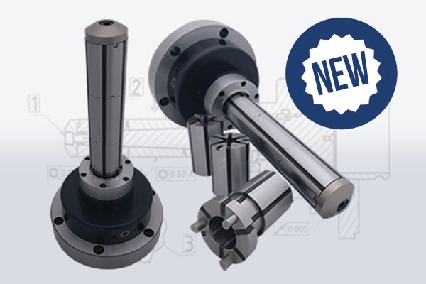
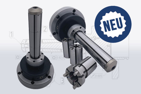
Special mandrel
Clamping diameter and clamping length at customer request
Suitable for series production or thin-walled workpieces which do not allow for deformation
Summary of the most important points
• Form-fitting clamping over the entire clamping range
• Clamp thin-walled workpieces without deformation
• Diameter and clamping length on customer request
• Exemptions on segment clamping bushes possible
• Segment clamping bushings secured against rotation
• System sealed against dirt
• Compatible with various NP systems or direct mounting
• Clamping with torque
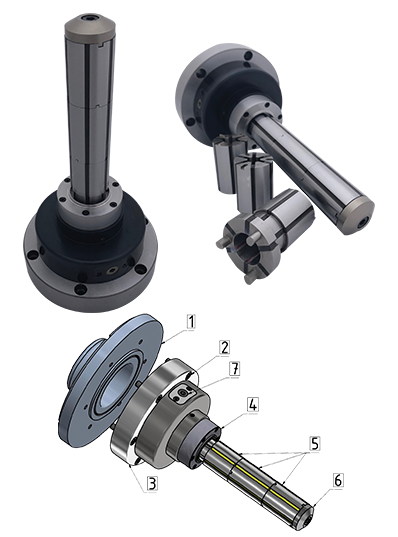
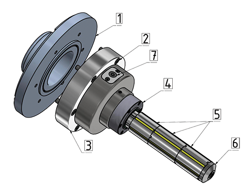
In detail
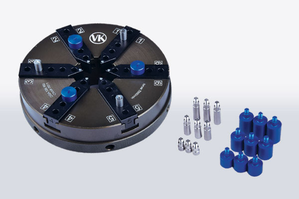
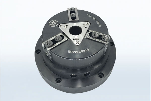
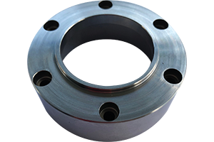
1. Spindle flange (Picture – Parotec)
2. Mounting mandrel (cylinder screws)
3. Mandrel body
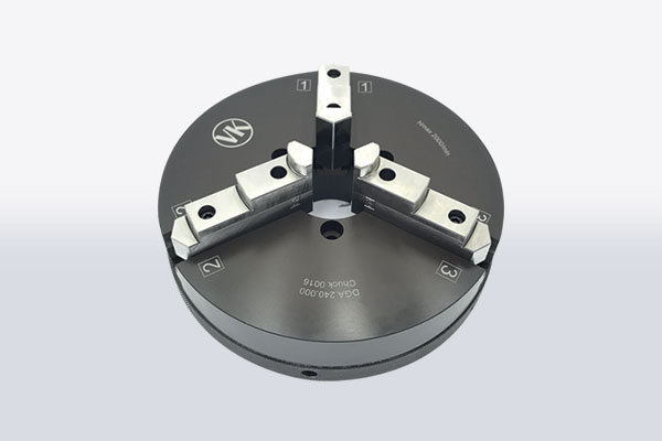
4. Workpiece stop
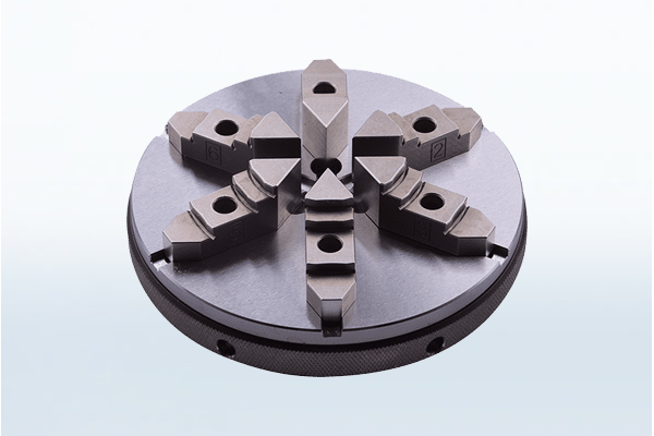
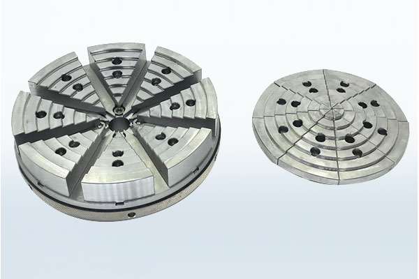
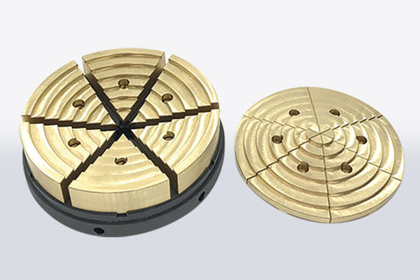
5. Segment clamping bushes
6. Clamping nut
7. Drive for ejector
Application
Milling and lathe machines
Cylindrical grinding
Sink erosion
Sizes
Customer specific – depending on the clamping task
Function description
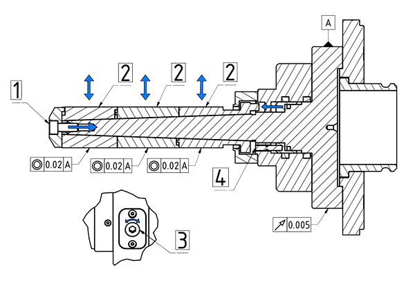
1. By screwing in the cylinder screw, the clamping nut presses on the segment clamping bushes.
2. The segment clamping bushes are forced on over the cone of the mandrel body and thereby the workpiece is clamped.
3. By screwing in the drive screw with an internal hexagon socket, oil is displaced in the piston chamber.
4. The piston with the ejector pins pushes the segment clamping bushes into the original position and the workpiece is released.
For an offer we require the following information:
1. Diameter of workpiece to be clamped
2. Length of workpiece to be clamped
3. Flange / NP system for mounting
4. Clamping accuracy
5. Clamping force (if known)
6. Manual clamping or via drawbar
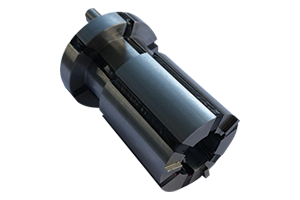
Segment clamping bushes are manufactured with a clamping diameter according to customer requirements. If the clamping device has several clamping bushes placed one above the other, they can only be mounted in one position.
The workpiece stop is manufactured with a stop dimension according to customer requirements. In the center, an elastomer is glued which presses on the segment clamping bushes. This seals the system against chips and dirt.
+ Thin-walled workpieces can be clamped in a positive-locking manner with torque without deformation
+ Inexpensive purchase
+ Short changeover and set-up time
- Automation hardly possible
- Possible source of error when clamping with incorrect torque
- Release (constriction) is done by hand
+ High process reliability during clamping
+ Short lead time when clamping and releasing workpiece
+ Direct mounting possible
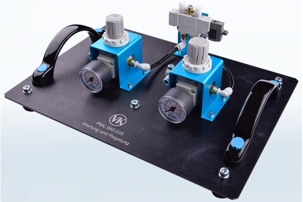
- Clamping force is defined by the hydraulic system (draw bar).
- For thin-walled workpieces an additional spring package is required to minimize the clamping force.
- Higher acquisition costs